Wireless temperature measurement unit

This I made as my Graduation theses.
In this project I was dealing with designing and construction of two radio modules for, as the name of this project says, temperature data colection, transmission an reception.
At the beginning, there was TMP05 sensor array and it´s purpose was to measure temperature along some industrial laser cutter. Problem was, that they have been using it to monitor temperature changes in nearby PC and the data was transferred through cables. Because it is highly impractical, I was told to redesign it.
The limiting criteria was, that transmitter together with its energy source was supposed to fit into 10.6 mm in diameter tube.
So starting from the energy source, I closed an AAA rechargeable battery, as it is only commercially available energy source with enough power and size that can fit. Voltage of 3.3V for microcontroller was assured by using step-up DC/DC converter LTC3525ESC6 from Linear Technology.
As a core of bought transmitter and receiver was chosen a CC430F5137 microcontroller from Texas Instruments, mainly for its supper low power consumption. It is really nice controller combining low power MSP430 and sub-1-GHz RF transceiver CC1101.
Antena is made by combination of Johanson Technology ceramic antenna and peace of PCB trace antenna. Because the antenna is asymmetric, I used a ballun filter.
Receiver was made similarly as transmitter. It communicate with a service computer ower the USB serial port. CC430 of course doesn´t support this serial protocol, so I found a UART to USB bridge CP2101 from Silicon Laboratories. Because of the power management module of CP2101 there was no problem with sourcing the receiver .
Bought transmitter and receiver was programmed trough Spy-Bi-Wire interface.
Program is using low power mode LPM4, when CPU, ACLK, MCLK and crystal is off, so the current is on its minimum while waiting for data transmission. Temperature is sensed once per second and the data in form of PWM from Daisy-chain connection of TMP05s is measured in transmitter. Measured data are radio transmitted on the frequency 868 MHz. After radio interrupt, the receiver wakes up and do its business with the received data. Then it goes to sleep for a while, until it gets an UART interrupt. Now, there is used an industrial protocol named Modbus for receiver-PC communication. So after the UART interrupt the receiver controls the received Modbus packet and analyze request. In this case there is used only a Modbus command 0x04, for registers reading. If the command is received, the receiver packetize the data received via RF for Modbus compatibility and sends them to PC. I was using simple application called Modbus Poll for checking the data, but it is compatible with any Modbus supporting software.
Maximum communication distance I measured was around 30 m over some glass doors along hallway. One 1000 mAh battery in transmitter should last at around one month (measured in workdays).
In title picture you can see the transmitter circuit. The receiver circuit differs in sourcing part and there is some different in peripheries.
There were only two prototype boards made in this project, one for transmitter and one for receiver. PCB layout was made in EAGLE cad software. They are double sided boards manufactured from GERBERs in one local factory and embedded by myself. Because of the manual embedding, I couldn´t make it much smaller, and I used from most part components with 0603 package. Just for an idea I enclosed picture of them bought.

The program was made in C language using Code Composer Studio from Texas Instruments.
If I could make it again, I would make it little different this time, especially speaking of PCB layout. But everything works just fine. Hope it will serve well.
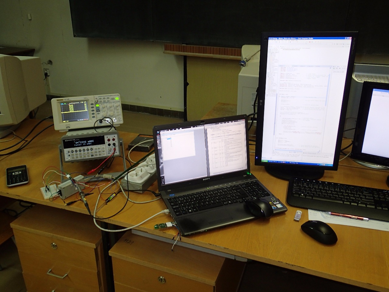
P.S.: A picture from my improvised lab.