Contactless identification RFID

Calculation of antenna impedance matching circuit for RFID reader was part of my Bachelor's theses.
This work is dealing with RFID technology and characterizes its construction and different kinds of its using possibilities. It also looks into designing and constructing of matching circuit of an antenna working at the frequency of 13,56 MHz in collaboration with the contactless reader/writer MFRC52302 and reviewing its functionality. It tells something about some possibilities of computer simulation of antennas used in similar systems and simulation of their S-parameters, in RFSim99, Sonnet and CST Microwave Studio software.
For starter, here´s something about RFID (Radiofrequency identification).
The whole system consists of few basic parts:
- RFID tag (or transponder) - includes antenna, some memory chip and in some cases a battery. You can probably find one of these even inside your dog.
- RFID reader - communicator, you can find on the wall, on your building´s entrance, or in hand of your postman. It includes antenna witch in some cases serves as power source for RFID tag.
- Software - something smart to handle modulation and demodulation and communication protocol.
There is many frequency bands, these things use. From 30 kHz up to 5.8 GHz. It depends on frequency the system use, if signal passes trough metals, water, wood or textile. The lower the frequency is, the better the troughpass. On the other hand, with higher frequency you can get higher datarate.
RFID usually uses one of two communication systems. The first one is inductive method and it is based on principle of transformer, where the primary coil generate high frequency electromagnetic field which reaches small distances, but big enough to source your RFID tag. It then send different signal back to your reader.
Second method is reflection method and uses Long Range or Far Field Communication. It is based on something similar to radar system. Antenna of RFID reader generates an energy which reaches the tag and after transformation it is used to source. Then the chip inside your tag switches on and off a little resistor and modulates antenna parameters. Reflected signal there for is logical 1 or 0 respectively. The difference between transmitted and reflected signal is the information.
That is just for the inspiration, RFID is widely documented topic so you can find many information and news for example in RFID Journal.
So anyway, my task was to calculate impedance matching circuit for RFID reader. My antenna had square shape with four winding coil. For the measurement I was using Hawlett Packard 8753A Network analyzer with 85046A S Parameter test set of the same brand. You can see my measurement results as S11 parameters on these pictures: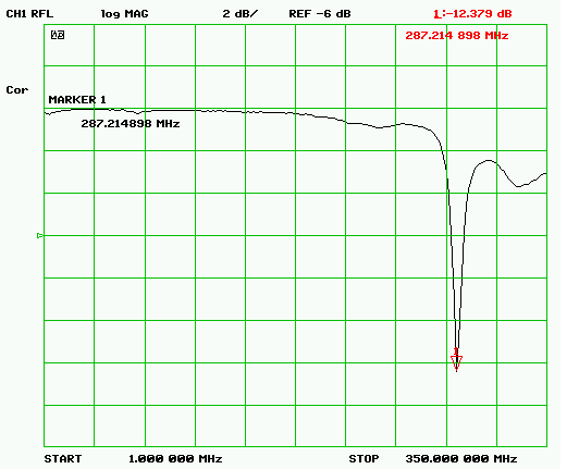
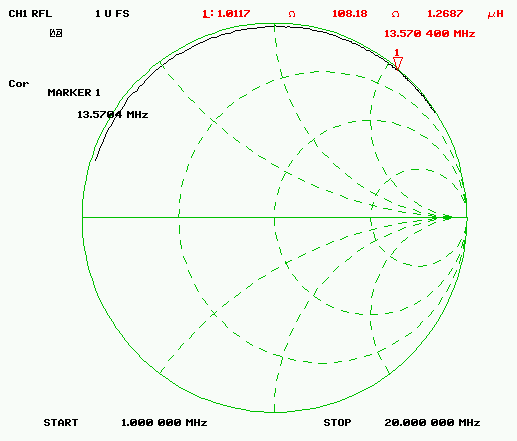
Marker on the first picture is set to self resonant frequency and as you can see it is around 287.21 MHz. The second picture shows serial induction and serial resistance of the antenna on13.57 MHz (which was the closest I could get marker to 13.56). These values allowed me to substitute real antenna with a serial circuit as on picture below.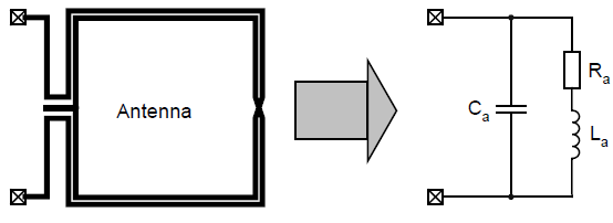
From this point, all you need to do is continue according to Antenna design guide for MFRC52X (MFRC523 was microcontroller used for this project), and with a little use of elementary math you can get to your results. The results was of course only theoretical and after few simulation (in for example RFSim99) made following tuning block diagram (in the same design guide), little soldering and few measurements I god acceptably good real results:
Marker in the S11 parameter measurement picture is set on 13.56 MHz, real part of impedance is 50.9 Ohm and imaginary part of impedance on the same frequency is almost zero.
My final circuit consisting of EMC filter, antenna and matching circuit, as i finally made it is shown below.
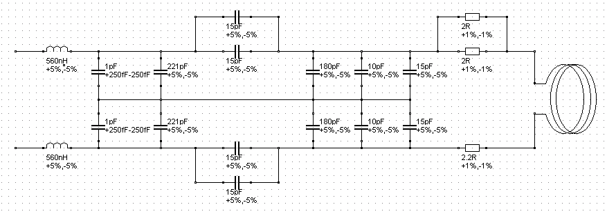
So that is pretty much it. Additionally there was some Sonnet and CST Microwave studio simulation involved, but the results was only for theoretical analysis and doesn´t really concern of the major topic.
Funny how this whole thing ended. After I done my work, I called my supervisor and left my finished antenna module on the working bench. Until these days he didn´t find it.
